
Administrator privileges will be needed for software and hardware installation.
This topic will guide you through preparing the chassis and installing the software for the DUT and TME. It includes the following sections:
Also refer to the README document for the calibration application for other useful information such as:
Known Issues
The README document can be found on the Keysight Technologies TME Calibration Software website.
|
|
Administrator privileges will be needed for software and hardware installation. |
Before running the N7870A Calibration Application, the software and drivers for thePXIe signal generator and the chassis must be installed. Refer to the PXIe signal generator Startup Guide for complete instructions. Current software, drivers, and documentation are available at Keysight support. Enter the model number at the top of the webpage and click  .
.
The Startup Guide will instruct you to:
Install the Keysight IO Libraries Suite (IOLS) available at: www.keysight.com/find/iosuite. This software must installed first. Refer to the PXIe signal generator Startup Guide for version requirements.
Install the chassis drivers (which are pre-installed on the embedded controller). Complete instructions are in the chassis Startup Guide. Chassis drivers, software, and manuals are also available at the Keysight support website.
If using an embedded controller, install it now and power up the chassis.
If using a remote host rather than an embedded controller, refer the Connecting a Remote Host PC to the Chassis section of the chassis Startup Guide for installation instructions and other requirements. The chassis Startup Guide can also be found on the Keysight support website.
Install the PXIe signal generator software and drivers which will also install the Soft Front Panel (SFP) of the PXIe signal generator. The software and drivers are available at the Keysight support website. If you encounter difficulties accessing software or drivers, contact csg.servicedesk@keysight.com for assistance.
Please note the following special cases:
M9383A: The M9383A signal generator will require two driver installations: its own driver and the driver package for the M938xA signal generators (models M9380A, M9381A, and M9389A). This is because the M9383A will need access to the M9300A frequency reference, and the driver for that module resides in the driver package for M938xA signal generators. To find the M938xA driver package, go to Keysight support and enter one of the M938xA model numbers: M9380A, M9381A, or M9389A.
M9383A with Option 1EB: M9383A signal generators with Option 1EB (increased output power) adds the M9405A amplifier module. TME needs to have access to that module's information, such as serial number and firmware revision. This requires that the IVI driver for the M9405A amplifier module be installed. The driver is available at the Keysight support website.
For instructions on how to verify the operation of the PXIe signal generator, refer to the Startup Guide located at the Keysight support website.
Use slot blockers and EMC filler panel in empty module slots to assure proper operating temperature.
At ambient temperatures above 45° C (113° F), set the chassis fan to High.
Position the chassis so that there is ample space between the chassis fan intake and exhaust vents. Blockage by walls or obstructions affects the air flow needed for cooling. (Refer to the chassis documentation for more information about cooling.)
A minimum of 50 mm (2 inches) of clearance should be provided in the front, rear, and sides of the chassis for ventilation. Depending on module power consumption, clearance may be needed below the chassis to accommodate the air intakes on the bottom of the chassis.
If you are using a remote controller and you have installed the interface cable, you must power up the chassis BEFORE you power up the PC. When you power down your chassis, shut down the PC before you power down the chassis.
It is recommended that your remote controller components match the manufacturer of your chassis to minimize compatibility issues.
PXI hardware does not support hot-swap capabilities (changing modules while power is applied to the chassis). Before installing the module into the chassis, power off the chassis to prevent damage to the module.
To avoid damage when handling the modules, do not touch the exposed connector pins.
Refer to the Readme.txt file for information on the compatibility of this package with previous versions of the application and the Test Management Environment (TME) test executive.
Refer to the Readme.txt for information on the minimum system requirements to run this application.
|
|
Installation packages are available for download at the Keysight Technologies Calibration website. |
There are two ways to install TME and its applications:
Network Installations — Equipment and test data information is stored in a central location (the TME Server). This data is shared among a set of TME Clients. Multiple test stations can then have access to this central information.
Local Installations — Everything is installed on one PC
In a network installation, order information is stored centrally and can be accessed by any TME client in the network. This allows you to combine data from tests that were run on multiple stations into a single report. Equipment data and order information are also accessible from any station.
|
|
|
To install an application on a network, follow these steps:
Find the PC where the TME network was installed (shows “TME Server” in Programs and Features).
Run Setup.exe for the application on that PC. This will install all networked components for that application.
Install application clients:
TME clients will be asked to install the application the next time TME is started.
or
Applications can be installed by running the setup file from the network directory:
\\FileServer\Test Management Environment\Install\(AppName)\(AppName)ClientSetup.exe
|
|
The client setup must be run from this location. It should not be moved or renamed. |
On a local installation, all application data is stored on the target PC. TME must be installed on the target PC before the application installation can occur. Once TME has been installed as a local installation, the application will automatically install locally when executed. Order information, test results, and equipment data will not be shared with other users.
To remove pre-E.01.00 versions of TME and its applications before installing a newer version, please refer to Installing Over Previous Versions.
|
|
If you uninstall TME completely or uninstall any TME application, you will lose the data associated with those applications. Create any reports needed and save them as PDF files before you perform any uninstallation of that product. |
To uninstall a previous version of TME, please see Installing over Previous Versions.
To uninstall TME or any TME application, select that package from Programs and Features on the Control Panel and click Uninstall.
To uninstall an application client, select that package from Programs and Features on the Control Panel and click Uninstall.
|
|
Data will not be lost if only a client is uninstalled. Other clients will still have access to the data in the network. |
To uninstall an application server:
Follow the directions above to uninstall all application clients first.
On the PC where the server installation was performed, select the application server from Programs and Features on the Control Panel and click Uninstall.
To uninstall an application local installation, select that package from Programs and Features on the Control Panel and click Uninstall.
The typical GPIB address configuration for a test station is:
|
Spectrum Analyzer |
18 |
|
Power Meter |
13 |
|
Frequency Counter |
3 |
|
Source |
19 |
|
Network Analyzer |
16 |
|
DVM |
22 |
|
Function Generator |
10 |
|
Oscilloscope |
4 |
Follow the steps below to manually check for proper connection of the GPIB devices before performing tests on a newly connected test station.
Note the GPIB address of each instrument associated with the test station/test plan defined earlier.
Connect a power cord to each instrument, and then connect each instrument to the computer serving as the GPIB controller.
Power up all the instruments on the GPIB bus.
Check each GPIB instrument for proper communication over the bus and the required detectable options. Follow the process described below.
|
|
When checking the basic operation of each instrument or when checking for detectable options on a given instrument, you may need to look up the actual command for retrieving the identification string before performing these steps. |
Start the Keysight Connection Expert from the task bar or access it through Start > All Programs > Keysight Connection Expert.
Check for all expected GPIB devices. Verify that all expected GPIB devices are shown in the left window. If a device is missing, correct the problem and re-scan for connected instruments.
Check for basic operation of each GPIB device:
|
|
If an instrument does not support SCPI, refer to the user guide for the product to learn more about checking the basic operation of its GPIB. |
Select a GPIB device.
Select the Interactive I/O from the right window.
The command window should be pre-populated with the *IDN? query. You can also select from the Commands > drop-down menu, or simply type *IDN? in the command window.
Select Send & Read.
Verify that the expected model number is contained in the response text string.
Check for detectable options on a given device:
|
|
This does not work with the power meter. |
Select a GPIB device to highlight it.
Select the Interactive I/O from the right window.
Type *OPT?
in the command window.
Select Send & Read.
Use the following steps to manually check for proper connection of LAN devices before performing tests on a newly configured test station.
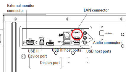
Verify that the device is connected to the LAN using the proper connector.
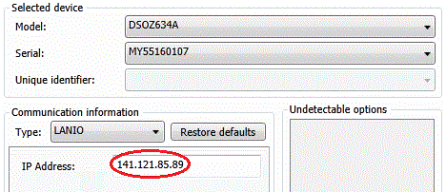
Determine the LAN address of the device. For the Infiniium Z-Series Oscilloscopes, this can be found under Utilities > Remote… > Web Address.
Ensure that the proper IP address has been configured for the device in TME.
Verify that the device can be detected in Keysight Connection Expert.
Start Keysight Connection Expert from the task bar or access it through Start > All Programs > Keysight Connection Expert.
If necessary, add a LAN interface using the Add Interface button at the top.
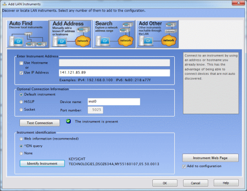
With the LAN interface selected, select Add Instrument.
Select Add Address.
Select Use IP Address and enter the IP address on the instrument.
Click Test Connection and verify that the instrument is detected.
Under Instrument Identification, select *IDN Query.
Click Identify Instrument and verify that the model and serial number are correctly reported.
Protection against ESD (electrostatic discharge) is essential while connecting, inspecting, or cleaning connectors attached to a static-sensitive circuit (such as those found in test sets). Static electricity can build up in your body and can easily damage sensitive internal circuit elements when discharged. Static discharges too small to be felt can cause permanent damage. Devices such as calibration components and units under test (UUTs) can also carry an electrostatic charge. To prevent damage to the test set, components and devices:
Always wear a grounded wrist strap having a 1 million Ohm resistor in series with it when handling components and devices or when making connections to the test set.
Always use a grounded antistatic mat in front of your test equipment.
Always wear a heel strap when working in an area with a conductive floor. If you are uncertain about the conductivity of your floor, wear a heel strap.

